English
 Español
 Deutsch
 Français
 عربي
عربي
Complete Guide to MCCB and DC MCCB: From Principles & Selection
Date:7/29/2026 2:23:39 PM Click:1
Table of Contents
1.What is an MCCB? Core Functions and Applications
2.AC MCCB vs DC MCCB: What's the Real Difference?
3.MCCB Selection Guide: Key Parameters Explained
4.MCCB Installation Steps and Critical Precautions
5.CNLONQ LQM1/LQM3 Series DC MCCB: Product Highlight
1. What is an MCCB? Core Functions and Applications
1.1 Definition and Core Components
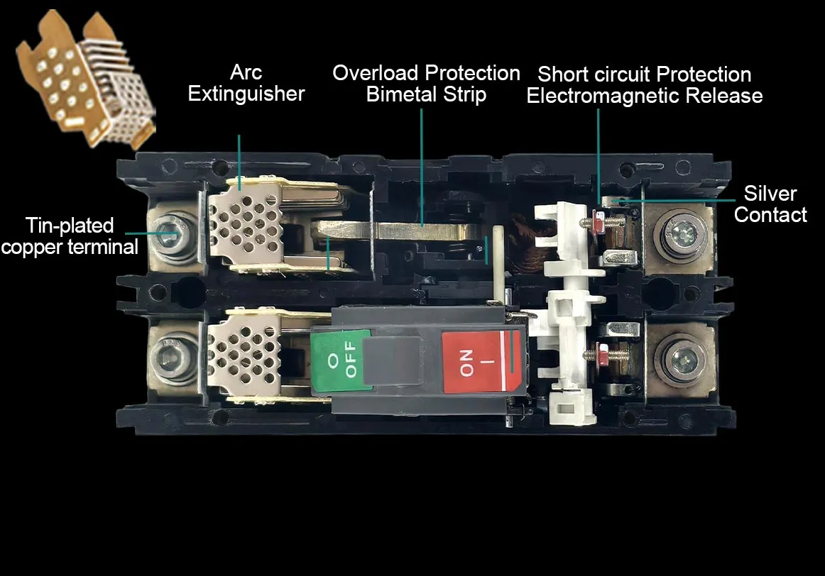
A Molded Case Circuit Breaker (MCCB) is a critical protective device in low-voltage power distribution systems. It gets its name because all core components — including the contact system, arc chute, operating mechanism, and trip unit — are enclosed within a molded insulating plastic housing.
Compared to Miniature Circuit Breakers (MCBs), MCCBs offer a wider rated current range and higher breaking capacity. They can meet multiple protection requirements from branch circuits to main distribution lines, earning them the reputation as "safety guardians" of industrial and commercial power systems.
Key components of an MCCB:
- Molded Case Housing: Made from flame-retardant, insulating, high-strength engineering plastics (such as DMC, SMC) with excellent insulation, flame resistance, dustproof, and moisture-proof properties
- Contact System: Responsible for making and breaking the circuit
- Arc Chute: Rapidly extinguishes the electric arc generated during breaking
- Operating Mechanism: Enables manual or motorized on/off operation
- Trip Unit: The heart of protection functionality, available in thermal-magnetic and electronic types
1.2 Core Protection Functions
MCCBs integrate control and multiple protection functions into a single device. Key capabilities include:
Overload Protection: Achieved through a bimetallic strip in the thermal-magnetic trip unit. When current continuously exceeds safe limits, the bimetallic strip heats up and bends, triggering the trip mechanism to open the circuit and protect wiring and equipment from overheating damage.
Short Circuit Protection: Implemented via an electromagnetic trip unit. When a short circuit fault occurs, the strong magnetic field generated by the fault current instantly drives the electromagnetic mechanism to act, breaking the circuit within milliseconds to contain the fault to the smallest possible scope.
Extended Protection Functions: Some models can be expanded with additional features such as earth leakage protection, undervoltage protection, and overvoltage protection to meet more complex system protection requirements.
1.3 Typical Application Fields
MCCBs are widely used in various medium-to-large capacity distribution scenarios. Typical applications include:
| Application Scenario | Specific Uses |
| Industrial Distribution | Factory main incoming panels, industrial control cabinets, motor feeder protection |
| Commercial Buildings | Large commercial switchboards, high-rise building main panels |
| Data Centers | Data center power distribution systems, UPS system protection |
| Energy Systems | Generator protection, PV combiner boxes, inverter DC side |
| HVAC Systems | Chiller units and large HVAC systems |
| Infrastructure | Rail transit, communication base stations, hospital power distribution systems |
Many people mistakenly assume that AC and DC circuit breakers differ only in voltage type. In reality, there are fundamental differences in arc extinction principles, structural design, and application scenarios — they must never be used interchangeably.
2.1 Arc Extinction Principle: The Core Difference
AC MCCB: Natural Arc Extinction via Zero-Crossing
Alternating current naturally crosses zero every half-cycle (100 times per second at 50Hz). When the current passes through zero, the arc briefly extinguishes. The breaker takes this opportunity to rapidly stretch the arc and cool the medium, preventing it from re-igniting before the current increases again. This makes AC arc extinction relatively straightforward, and the arc chute structure is simpler.
DC MCCB: Forced Arc Extinction with Higher Technical Barriers
Direct current has no zero-crossing points — the current is constant. Once an arc forms, it burns continuously and steadily at extremely high temperatures and will not extinguish on its own. DC circuit breakers must rely on specialized reinforced arc extinction systems to forcibly stretch, cool, and interrupt the arc.
DC MCCB arc extinction technology features:
- Larger Arc Chute: Increased number of arc splitter plates and volume
- Permanent Magnetic Blowout Technology: Uses magnetic fields generated by permanent magnets to rapidly blow the arc into the arc chute
- Wider Contact Gap: Greater distance between moving and fixed contacts
- Special Contact Materials: Alloy materials more resistant to arc erosion
2.2 Other Key Differences Compared
| Comparison Dimension | AC MCCB | DC MCCB |
| Arc Extinction Method | Relies on current zero-crossing standard arc chute | Permanent magnetic blowout multi-stage reinforced arc chute |
| Polarity Requirement | Non-polarized, can be wired in any direction | Most are polarized, strict positive/negative terminal distinction required |
| Rated Voltage | AC230V/400V/690V, etc. | DC500V/1000V/1500V, etc. |
| Contact Material | Silver-nickel or silver-graphite alloys | Special alloys with higher arc erosion resistance |
| Application Scenarios | AC distribution, motor protection, etc. | PV systems, energy storage, DC distribution |
| Cost | Relatively lower | More precise structure, higher cost |
⚠️ Safety Warning: AC circuit breakers must NEVER be used in DC circuits! Due to insufficient arc extinction capability, the arc cannot be extinguished during breaking, which can destroy equipment and even cause explosions and fires.
3. MCCB Selection Guide: Key Parameters Explained
Proper selection is the first step to ensuring safe and reliable circuit breaker operation. Choosing the wrong parameters can lead to protection failure or equipment damage. Below are the core parameters and selection principles for MCCBs.
3.1 Rated Current (In)
Definition: The current value that the circuit breaker can continuously carry under long-term operation.
Selection Principles:
- Determined based on the actual load current of the circuit, typically 1.1–1.3 times the calculated load current
- Consider ambient temperature: derating required in high-temperature environments
- Must match cable ampacity to prevent cable overheating
Calculation Formula Reference:
- Single-phase circuit: I = P / (V × PF)
- Three-phase circuit: I = P / (√3 × V × PF)
3.2 Rated Operational Voltage (Ue)
Definition: The nominal voltage value at which the circuit breaker can operate normally.
Selection Principles:
- Must be ≥ the maximum system operating voltage
- Pay attention to distinguishing between AC/DC systems; DC circuit breakers require specialized design
- DC systems require special attention to system voltage levels (e.g., DC500V, DC1000V, DC1500V)
3.3 Breaking Capacity (Icu / Ics)
Breaking capacity is the core indicator measuring a circuit breaker's short-circuit protection capability, divided into two ratings:
Ultimate Breaking Capacity (Icu): The maximum short-circuit current that the circuit breaker can interrupt. After breaking, continued operation is not guaranteed.
Service Breaking Capacity (Ics): The short-circuit current value at which the circuit breaker can continue normal operation after breaking. Typically 50%–100% of Icu.
Selection Principles:
- Icu must be greater than the prospective short-circuit current at the installation point
- For critical loads or scenarios requiring rapid power restoration after faults, select the highest possible Ics (100% Icu recommended)
- For locations with high short-circuit currents such as transformer outlet cabinets, prioritize high breaking capacity ratings
3.4 Frame Size
Definition: The maximum rated current that the breaker's housing frame can support, representing the current class of the series.
Common Frame Sizes: 63A, 100A, 160A, 250A, 400A, 630A, 800A, 1250A, etc.
Selection Note: Within the same frame size, trip units with different rated currents can be configured. For example, a 250A frame can be configured with 100A, 160A, 200A, 250A, and other rated currents.
3.5 Trip Unit Types
Thermal-Magnetic Trip Units:
- Simple structure, high reliability, low cost
- Overload protection (thermal) short circuit protection (magnetic)
- Relatively fixed setting range
- Suitable for most conventional distribution scenarios
Electronic Trip Units:
- Richer protection functions (L-long time delay, S-short time delay, I-instantaneous, G-ground fault)
- High setting accuracy, wide adjustable parameter range
- Enables selective protection coordination
- Suitable for critical applications requiring high protection precision
3.6 Pole Selection
- 1P: Single pole, used for phase protection in single-phase circuits
- 2P: Double pole, used for phase neutral in single-phase circuits, or positive negative in DC systems
- 3P: Three poles, used in three-phase three-wire circuits
- 4P: Four poles, used in three-phase four-wire circuits, or multi-pole series connection in DC systems for voltage boosting
3.7 Three-Step Selection Method
Step 1: Determine Basic Parameters
- System voltage (AC/DC, voltage level)
- Calculate load current
- Estimate short-circuit current level
Step 2: Select Protection Functions
- Basic protection: Thermal-magnetic type is sufficient
- Precision protection: Choose electronic trip unit
- Special requirements: Earth leakage, undervoltage, and other additional functions
Step 3: Verify Installation Conditions
- Installation method (fixed / plug-in / withdrawable)
- Installation space dimensions
- Ambient temperature and protection degree requirements
4. MCCB Installation Steps and Critical Precautions
Proper installation is the foundation for reliable MCCB operation. Improper installation can lead to poor contact, overheating, false tripping, or even safety accidents.
4.1 Pre-Installation Preparation
Checklist:
- Verify that the circuit breaker model and parameters match the design requirements
- Inspect the appearance for damage, rust, and confirm all accessories are complete
- Confirm that the installation location environmental conditions (temperature, humidity, dust, etc.) meet requirements
- Prepare installation tools: torque wrench, screwdriver, wire stripper, multimeter, etc.
Environmental Requirements:
- Ambient temperature: Typically -5°C to 40°C
- Installation altitude: Generally not exceeding 2000m (derating required at high altitudes)
- Free from severe vibration, corrosive gases, and conductive dust
4.2 Detailed Installation Steps
Step 1: Mount the Circuit Breaker Body
- Mark positions on the mounting plate or rail based on installation hole dimensions
- For DIN rail mounting: First hook the upper part of the breaker onto the rail, then press down to lock the lower clip
- For screw mounting: Tighten with matching bolts to ensure secure, wobble-free installation
- When installing multiple units side by side, maintain sufficient spacing (≥10mm recommended) for heat dissipation
Step 2: Wiring Operation
- Conductor Selection: Wire cross-section must match the circuit breaker rated current to ensure sufficient ampacity
- Stripping: Strip insulation to an appropriate length, ensuring the metal portion is fully inserted into the terminal with no exposed conductors
- Wiring Sequence: Follow the "top-in, bottom-out" principle — power supply connects to the upper end (line side), load connects to the lower end (load side)
- Phase Sequence: Three-phase breakers follow A, B, C phase sequence; DC systems strictly distinguish positive and negative poles
- Torque Tightening: Use a torque wrench to tighten terminals to the specified torque for good contact
Step 3: Accessory Installation (If Applicable)
- Install shunt releases, auxiliary contacts, alarm contacts, undervoltage releases, and other accessories per the manual
- Pay attention to left/right accessory chamber positioning — do not install reversed
- Connect accessory wiring correctly according to markings; control circuit voltage must match
Step 4: Insulation Check and Testing
- Measure insulation resistance using a 500V or 1000V megohmmeter — should be ≥1MΩ
- Check insulation between poles and between each pole and the housing
- Confirm no short circuits, ground faults, or other hidden dangers
Step 5: Power-On Commissioning
- First perform no-load test: After closing, check that the breaker status indication is normal
- Measure voltage at line and load terminals to confirm normal voltage
- Gradually increase load and observe operation
- If conditions permit, perform trip tests to verify protection functionality (observe safety precautions)
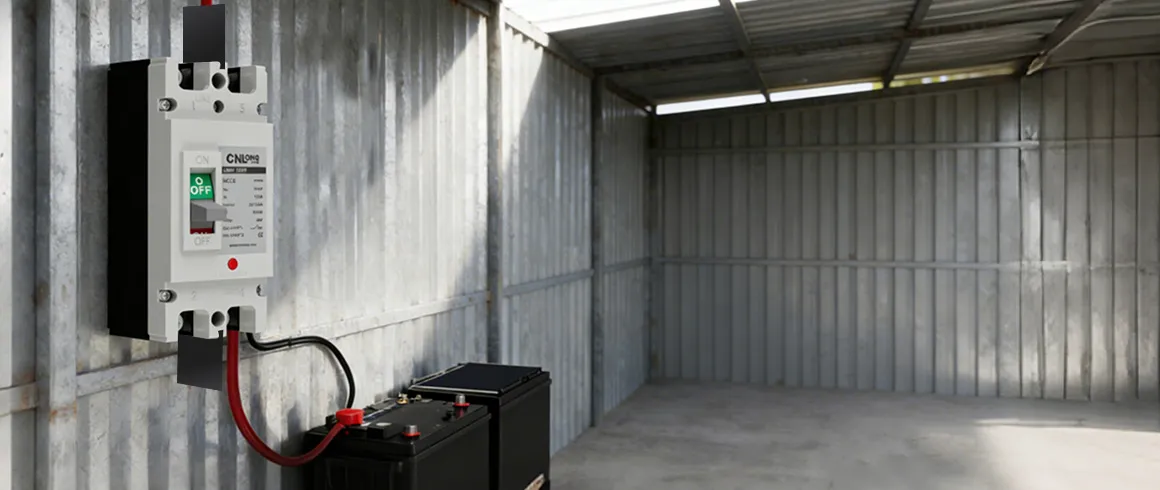
4.3 Key Precautions
Wiring Safety:
- ⚠️ Must operate with power OFF — live wiring is strictly prohibited
- Ground wire does not pass through the breaker; connect separately to the ground busbar
- Stranded flexible wire is recommended to be crimped with terminals before connection
- Clean debris inside the cabinet after wiring to prevent foreign object short circuits
DC System Special Notes:
- Strictly distinguish positive and negative poles, wire correctly according to " " and "-" markings
- Polarized DC circuit breakers must not be reverse-connected
- When using multi-pole series connection for voltage boosting, ensure all poles operate synchronously
Operation and Maintenance:
- Regularly check wiring terminals for overheating or discoloration
- Periodically clean the breaker surface and arc chute dust accumulation
- After fault tripping, identify the cause and clear the fault before reclosing
- Conduct regular operation tests to ensure flexible and reliable mechanism
5. CNLONQ LQM1/LQM3 Series DC MCCB: Product Highlight
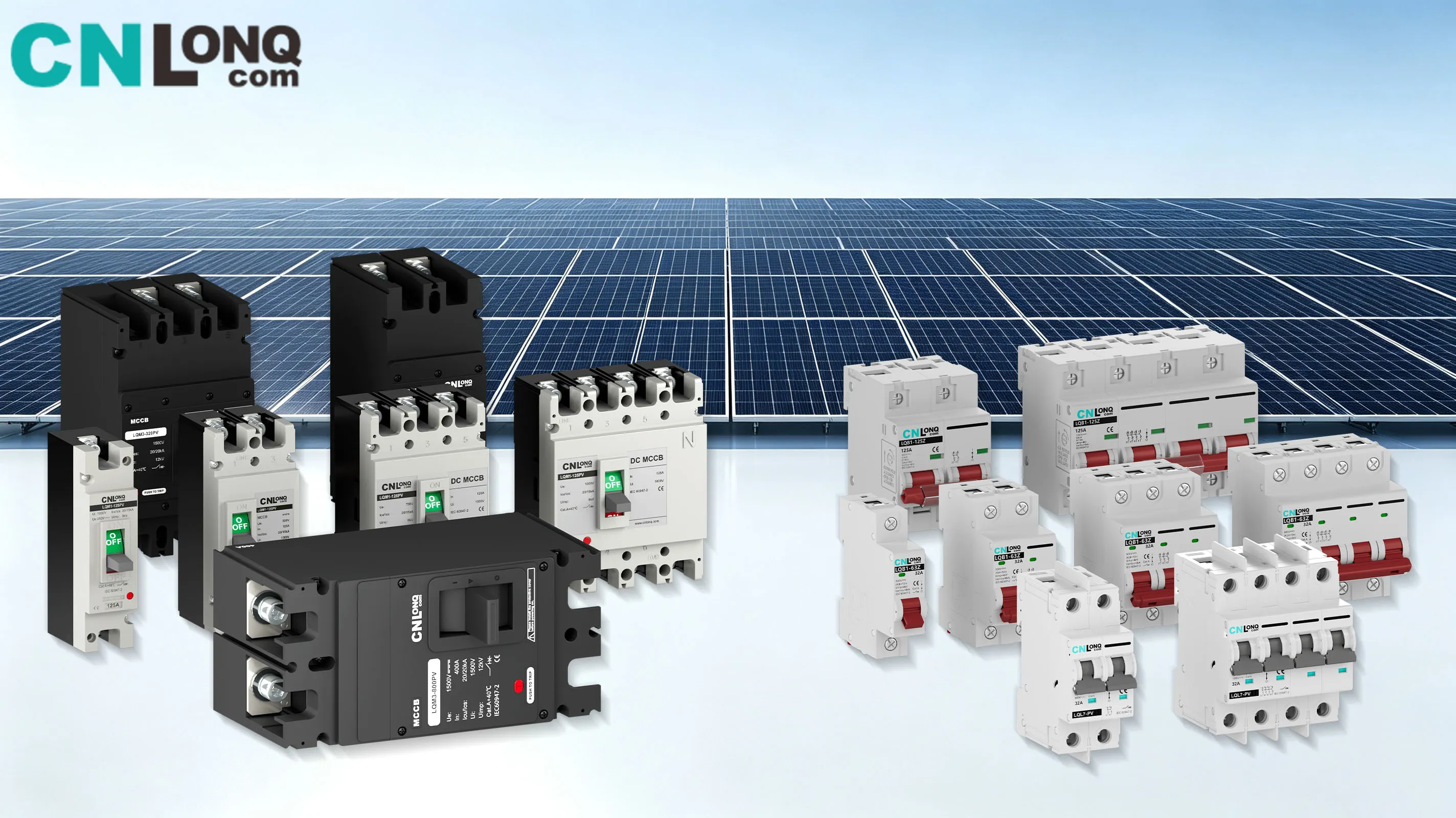
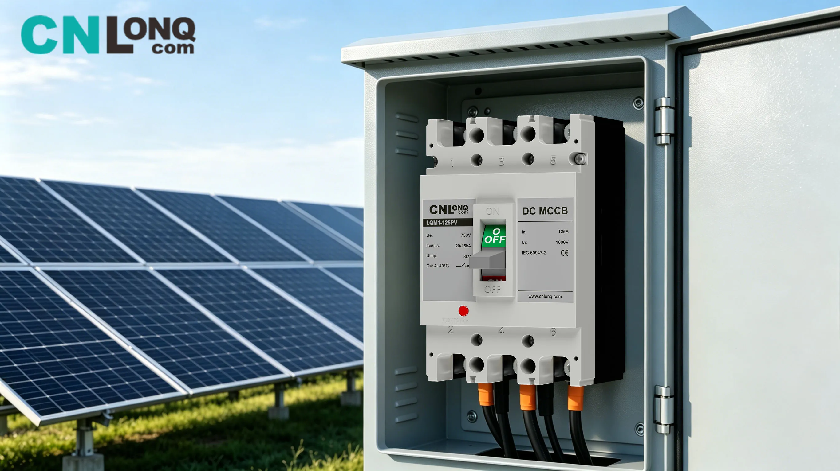
In today's rapidly developing DC systems for photovoltaics and energy storage, choosing a reliable DC molded case circuit breaker is crucial. The LQM1/LQM3 Series DC MCCB from CNLONQ, specifically optimized for DC systems, is the ideal choice for PV combiner boxes, inverters, energy storage systems, and more.
5.1 Core Product Specifications
| Parameter | LQM1/LQM3 Series Specifications |
| Rated Operational Voltage | Full series coverage from DC500V to DC1500V |
| Rated Current Range | Wide selection from 63A to 800A |
| Pole Configuration | Flexible options: 1P / 2P / 3P / 4P |
| Breaking Capacity | High rated short-circuit breaking capacity, meeting mainstream PV system requirementsOverload long-time delay protection short-circuit instantaneous protection |
| Protection Functions | Overload long-time delay protection short-circuit instantaneous protection |
| Trip Type | Thermal-magnetic trip, high reliability |
5.2 Technical Advantages
Professional DC Arc Extinction System
- Arc chute design specifically optimized for the DC no-zero-crossing characteristic
- Adopts permanent magnetic blowout technology to rapidly drive the arc into the arc chute
- Multi-stage arc splitter plate design effectively stretches, cools, and interrupts the arc
- Reliable breaking under DC1500V operating conditions, ensuring system safety
Wide Voltage and Current Coverage
- Voltage range from DC500V to DC1500V, adapting to PV systems of different scales
- Current range from 63A to 800A, covering full scenario requirements from branches to mains
- Multiple pole configurations from 1P to 4P, flexibly meeting system design requirements
High Reliability Design
- Resin housing with excellent insulation performance
- High-quality contact materials resistant to arc erosion for long service life
- Precision trip mechanism with accurate action and good consistency
- Suitable for complex environmental conditions such as outdoor and desert locations
Easy Installation and Maintenance
- Standard installation dimensions for convenient cabinet layout
- Well-designed terminal blocks for easy installation
- Modular structure for flexible accessory expansion
- Clear status indication for convenient operation and maintenance
5.3 Typical Application Scenarios
PV Power Station DC Side
- PV combiner box input/output protection
- Inverter DC side protection
- DC distribution cabinet main switch / branch switch
- Suitable for large ground-mounted power stations and commercial & industrial rooftop PV
Energy Storage Systems
- Battery cluster protection
- PCS (Power Conversion System) DC side
- DC busbar protection
Other DC Systems
- DC charging piles
- Communication base station DC distribution
- Industrial DC drive systems
5.4 Selection Recommendations
For different application scenarios, the following selection references are recommended:
| Application Scenario | Recommended Voltage Level | Recommended Current Range | Recommended Poles |
| PV String Branches | DC1000V/1500V | 63A~125A | 2P |
| PV String Branches | DC1000V/1500V | 200A~400A | 2P/4P |
| Inverter DC Side | DC1000V/1500V | 400A~800A | 2P/4P |
| Energy Storage Battery Clusters | DC500V/1000V | 100A~400A | 1P/2P |
| DC Charging Piles | DC500V/750V | 63A~200A | 2P |
Note: Specific selection must be determined based on actual system parameters and short-circuit current calculation results. CNLONQ's technical team can provide professional selection support.
Conclusion
As core protective components in low-voltage power distribution systems, the selection and installation of molded case circuit breakers directly relate to the safe and reliable operation of the entire system. Especially in DC systems, due to the difficulty of arc extinction and high technical requirements, professional DC MCCB products are essential.
The CNLONQ LQM1/LQM3 Series DC MCCB, with professional DC arc extinction technology, wide parameter coverage, and high reliability design, can meet full-scenario DC protection requirements from DC500V to DC1500V and 63A to 800A — making it the reliable choice for new energy systems such as photovoltaics and energy storage.
For more product details or technical support, welcome to contact the CNLONQ professional team.
This article is for technical reference only. Please refer to the product manual and relevant standards for specific selection and installation.