English
 Español
 Deutsch
 Français
 عربي
عربي
Complete Guide to Residential PV Combiner Boxes: Selection, Wiring & Troubleshooting How to Choose the Right PV Combiner Box for Your Home
Date:7/21/2026 10:36:24 AM Click:297
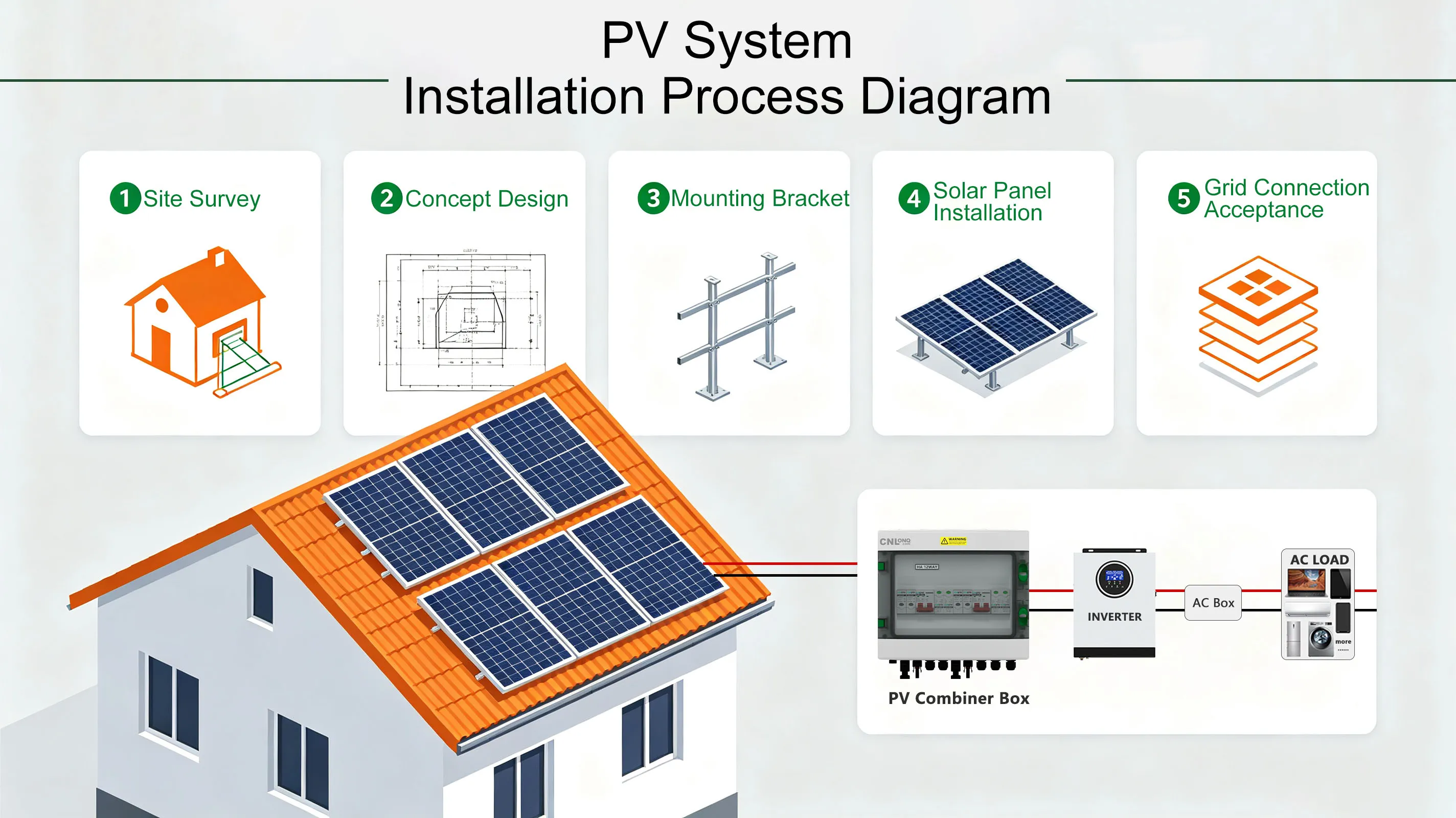
A PV combiner box serves as the "power distribution hub" of a residential solar system. It consolidates DC power from multiple PV strings and delivers it to the inverter, while providing overcurrent protection, surge protection, and other safety features. Choosing the right combiner box is the first step toward safe and efficient system operation.
1. Number of Inputs: Match Your Needs with Room to Spare
Select a combiner box with the appropriate number of input channels based on the number of PV strings in your system. Common configurations include 4-in-1-out, 6-in-1-out, 8-in-1-out, and 12-in-1-out.
Selection Principle: The number of inputs should be ≥ the actual number of strings. We recommend reserving 1-2 spare inputs for future expansion. For example, if your home has 6 PV panels, an 8-input combiner box is the more prudent choice.
2. Rated Voltage: Choose Higher Rather Than Lower for Safety Margin
The rated voltage of the combiner box must be ≥ the maximum DC voltage of the system. PV module open-circuit voltage increases in cold weather, so sizing based solely on normal operating voltage is insufficient.
Small residential systems: Typically DC 500V class
- Medium residential/commercial systems: Commonly DC 1000V class
- Large utility-scale systems: Often DC 1500V class
Important Note: Never use a lower-voltage combiner box in a higher-voltage system, as this can lead to insulation breakdown and equipment failure.
3. Rated Current: Precise Calculation for Safety Assurance
The fuse rating for each input should be ≥ 1.25 × the module short-circuit current (Isc). For example, if the module Isc is 10A, a 15A fuse should be selected for each input.
Total output current is approximately the sum of all input currents multiplied by a diversity factor (0.8-1.0), and the main breaker rated current must exceed the maximum output current.
4. Protection Rating: IP65 or Above for Outdoor Installation
Residential PV combiner boxes are mostly installed outdoors, requiring a minimum protection rating of IP65 to effectively resist dust, water, and UV radiation. For coastal or highly polluted areas, stainless steel enclosures or special anti-corrosion coating products are recommended.
5. Core Protection Features: Non-Negotiable Safety Baseline
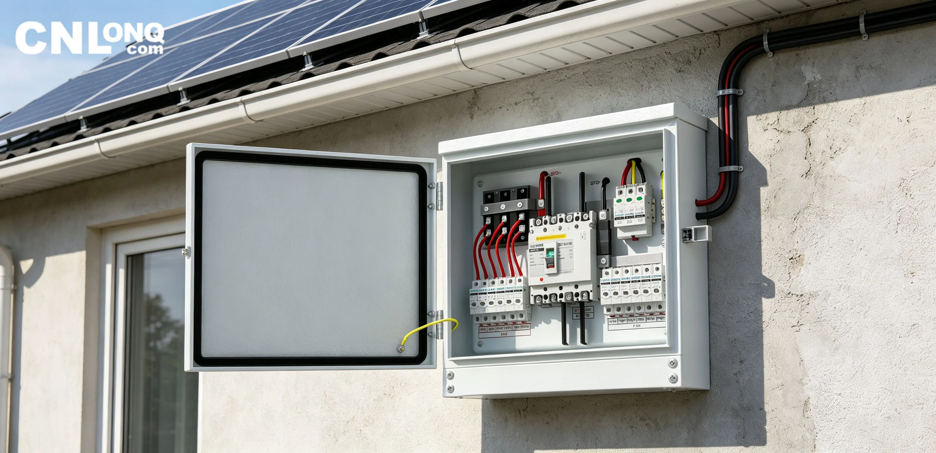
A high-quality combiner box should include the following protection configurations:
- DC Fuses: Independently configured for each input, quickly isolating fault branches in case of short circuit
- DC Breaker/Disconnect Switch: Installed on the output side for safe power isolation during maintenance
- Surge Protective Device (SPD): Protects against lightning strikes and grid surges, safeguarding expensive downstream inverter equipment
- Blocking Diodes (some models): Prevents reverse current draw from faulty strings
6. Smart Monitoring: Enhanced O&M Efficiency
Mid-to-high-end combiner boxes feature smart monitoring capabilities, enabling real-time tracking of per-string current, voltage, and internal box temperature, with data upload via RS485, Ethernet, and other methods. Users can remotely monitor each string's generation status and quickly identify anomalies, significantly reducing operation and maintenance costs.
PV Combiner Box Wiring Standards and Procedures
Proper wiring is the foundation of safe combiner box operation. Below is the standard wiring process, recommended to be performed by a licensed electrician.
Pre-Wiring Preparation
- Verify Specifications: Confirm the combiner box's number of inputs, rated voltage, and current match the design
- Inspect Enclosure: Ensure no deformation or damage, and that door locks and hinges are intact
- Prepare Tools: Multimeter, insulation resistance tester, crimping tool, torque wrench, screwdrivers, etc.
- Safety First: Ensure all PV strings are disconnected or at zero voltage before wiring
Step 1: Enclosure Mounting
- Securely mount the combiner box to a wall or support structure using expansion bolts
- Install the enclosure vertically, with a tilt angle not exceeding 5°
- Recommended mounting height: enclosure center 1.4-1.6 meters above ground for easy operation and maintenance
- Reliably connect the enclosure grounding terminal to the system grounding grid (ground resistance ≤ 4Ω)
Step 2: DC Input Wiring (PV String Side)
- Connect each string's positive cable to the corresponding positive input terminal (marked " " or red terminal)
- Connect each string's negative cable to the corresponding negative input terminal (marked "-" or black terminal)
- Use professional crimping tools for cold-pressed terminals to ensure secure, low-resistance connections
- When feeding cables into the enclosure, ensure cable entry holes are smooth and burr-free; metal enclosures require insulating bushings
- Route positive and negative cables separately to avoid cross-winding
- Confirm fuses are installed for each circuit (verify fuse ratings in advance)
Step 3: DC Output Wiring (Inverter Side)
- Connect the combiner box main output positive cable to the positive output terminal
- Connect the main output negative cable to the negative output terminal
- Output cable gauge must carry the maximum output current, not less than the gauge corresponding to the main breaker rated current
- Output cables are recommended to be run in conduit to prevent mechanical damage
Step 4: Surge Protection Grounding Wiring
- Reliably connect the SPD grounding terminal to the internal grounding busbar
- Connect the grounding busbar to the main system grounding grid via dedicated grounding cable
- Grounding cable cross-section: minimum 16mm² for copper, or per design requirements
Step 5: Communication Wiring (Smart Combiner Boxes)
- Connect communication cables (RS485, Ethernet, etc.) per the manual
- Run communication cables separately from power cables to avoid interference
- Ground communication cable shielding at one end only
Step 6: Wiring Verification and Power-On Testing
- Continuity Check: Use a multimeter to check each input for short circuits or reverse polarity
- Voltage Measurement: Measure main output positive-to-negative voltage, confirming it meets expectations
- Insulation Test: Positive/negative-to-ground insulation resistance should be > 1MΩ (500V megohmmeter)
- Terminal Tightening: Confirm all terminals are securely tightened with no looseness
- Sequential Power-Up: Close each string's fuse or breaker one by one, measuring each input voltage
- Close Main Breaker: Close the main output breaker, observe operating status, checking for abnormal heating or unusual noise
- Communication Verification: For monitored combiner boxes, confirm communication is working and data is uploading correctly
Step 7: Labeling and Finalization
- Apply clear circuit number labels to each input circuit (matching design drawings)
- Record initial voltage and current values for each circuit as a baseline for future maintenance
- Affix "DANGER: High DC Voltage!" warning label on the exterior of the enclosure
- Close and lock the enclosure door, and clean up the work site
Common PV Combiner Box Faults and Troubleshooting Methods
Combiner boxes operate long-term in outdoor environments and may experience various faults due to temperature, humidity, lightning, and other factors. Mastering common fault troubleshooting methods can quickly restore system power generation.
Safety Prerequisites for Troubleshooting
Before troubleshooting, always disconnect the combiner box DC switch and inverter-side switch, perform voltage testing, and implement grounding measures to prevent electric shock!
1. Fuse Blowout
Symptoms: No current/voltage on a branch, system generation output drops
Possible Causes:
- String short circuit or abnormal reverse current
- Module failure causing overcurrent
- Fuse aging or mismatched specifications
Solutions:
- Replace with a DC fuse of the same specification (must use DC-specific fuses with gPV characteristic)
- Inspect the corresponding string for short circuits, module damage, and other issues; resolve the fault before re-energizing
- Confirm fuse rated current matches module parameters (≥ 1.25 × Isc)
2. Loose/Oxidized Wiring Terminals
Symptoms: Terminal heating, burning odor, branch current unstable or low
Possible Causes:
- Insufficient torque during wiring, loosening over time
- Terminal oxidation due to humid outdoor environments
- Mismatched cable gauge, insufficient contact area
Solutions:
- Tighten terminals after power-off, using a torque wrench per terminal specifications (M6 terminals: 8-10N·m, M8 terminals: 12-15N·m)
- For severely oxidized terminals, polish the oxidation layer or replace cable terminals
- Verify cable gauge meets ampacity requirements
3. Surge Protective Device (SPD) Failure
Symptoms: SPD status window turns red, or surge protector is damaged
Possible Causes:
- Lightning strike or grid surge impact
- Natural aging from long-term operation
Solutions:
- Replace with the same model surge protector
- Check if grounding system is sound, whether grounding cables are loose or broken
- In high-lightning areas, consider upgrading SPD class
4. Water Ingress/Internal Condensation
Symptoms: Water droplets, water accumulation inside the box, rust on metal components
Possible Causes:
- Aging and failure of sealing gaskets
- Waterproof cable glands not tightened or missing
- Improper enclosure installation location, rainwater backflow
Solutions:
- After power-off, thoroughly dry the enclosure interior (use cool setting on hair dryer or fan)
- Clean rust and reapply anti-rust grease
- Replace aging sealing gaskets, tighten all waterproof cable glands
- Replace damaged components caused by severe water ingress
- Optimize installation location to avoid direct rain 冲刷
5. Communication Interruption/Data Anomalies
Symptoms: No data or abnormal data on monitoring platform
Possible Causes:
- Loose, reversed, or oxidized communication cables
- Device address conflicts
- Acquisition module failure or power supply damage
- Electromagnetic interference (communication cables routed in same trench as DC cables)
Solutions:
- Check communication cable connections, confirm A/B lines are not reversed
- Verify device addresses, resolve conflicts
- Measure acquisition module supply voltage (normal ~15V); replace power module if no output
- Route communication cables separately from power cables, maintaining safe distance
6. Low Branch Current
Symptoms: One branch current significantly lower than other branches
Possible Causes:
- Module shading (dust, bird droppings, leaves, etc.)
- Module hot spot effect or PID effect
- Poor contact at connections or MC4 connectors not fully engaged
- Module damage
Solutions:
- Clean obstructions from module surfaces
- Check if MC4 connectors are fully engaged and show no signs of burning
- Use infrared thermal imaging to inspect modules for hot spots
- Enable PID recovery function at night (if system supports it)
- Replace damaged modules if confirmed faulty
CNLONQ PV Combiner Boxes: Reliable Power Protection for Homes Worldwide
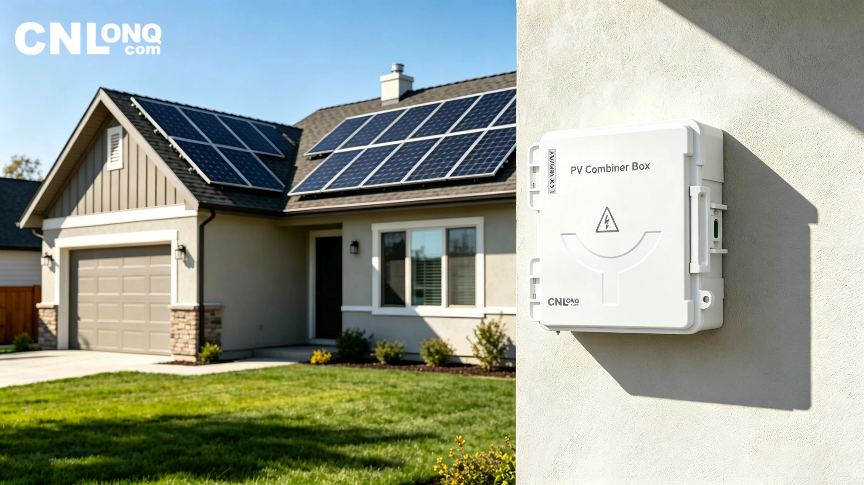
CNLONQ (Wenzhou Longqi New Energy) specializes in PV electrical solutions. Our combiner box products are exported to countries and regions worldwide, widely applied in residential, commercial & industrial, and large utility-scale solar projects.
Core Product Advantages
1. Full Series Configuration, Flexible Adaptation
- Available in plastic and metal enclosure options
- Input channels ranging from 1 to 16 strings, supporting 500V, 1000V, and 1500V full voltage classes
- Customizable configurations based on customer requirements to meet diverse residential and project needs
2. IP65 Industrial Protection, Adaptable to Global Climates
- Full product line achieves IP65-IP66 protection rating, effectively dustproof and waterproof
- Cold-rolled steel enclosures with special anti-corrosion treatment, resistant to humidity and salt spray, suitable for harsh environments such as coastal areas and Gobi deserts
- Core components operating temperature range of -40°C to 85°C, unphased by extreme heat and cold
3. Multiple Safety Protections, Safeguarding System Stability
- Independent DC fuses for each string, precisely isolating fault branches
- High-quality DC circuit breakers with strong breaking capacity and reliable operation
- DC surge protective devices effectively resisting lightning strikes and surge impacts
- Key components certified to international standards including CE and ROHS, ensuring quality
4. Smart Monitoring, Worry-Free O&M
- Integrated current sensing and RS485 communication enable real-time per-string current monitoring
- Supports fault localization and remote alarm, significantly reducing O&M costs
- Particularly suitable for centralized management of remote areas or distributed solar systems
Typical Application Case
CNLONQ PV combiner boxes have been successfully deployed in a 200MW Gobi solar project in Saudi Arabia, operating stably in extreme high-temperature and heavy-sand harsh environments, fully validating product reliability and adaptability.
Choose CNLONQ, Choose Reliability. Whether for residential rooftop or utility-scale solar farms, CNLONQ provides professional, safe, and efficient PV combiner box solutions.
For more product information, please contact: sales@cnlonq.com