 English
 Español
 Deutsch
 Français
 عربي
عربي
Reinforcing PV DC‑Side Safety: Mitigating DC Fire Risks, Lightning Protection and Key Component Selection
With the large‑scale deployment of distributed and utility‑scale photovoltaic systems, high‑power solar modules have become mainstream, alongside 1000 V and 1500 V high‑voltage DC systems. As long as sunlight is available, the PV DC side remains energized. Unlike AC circuits where arcs self‑extinguish at current zero‑crossing, DC faults can generate persistent electric arcs — the leading cause of PV plant fires. Statistics show most photovoltaic fires originate on the DC side. Failures in combiner boxes, DC cables, connectors, DC disconnectors and surge protective devices (SPDs) create safety hazards and financial losses for residential, commercial‑industrial and utility‑scale installations. Effective DC‑side risk control, robust lightning protection and proper DC component selection are critical throughout design, procurement, installation and O&M of PV projects.
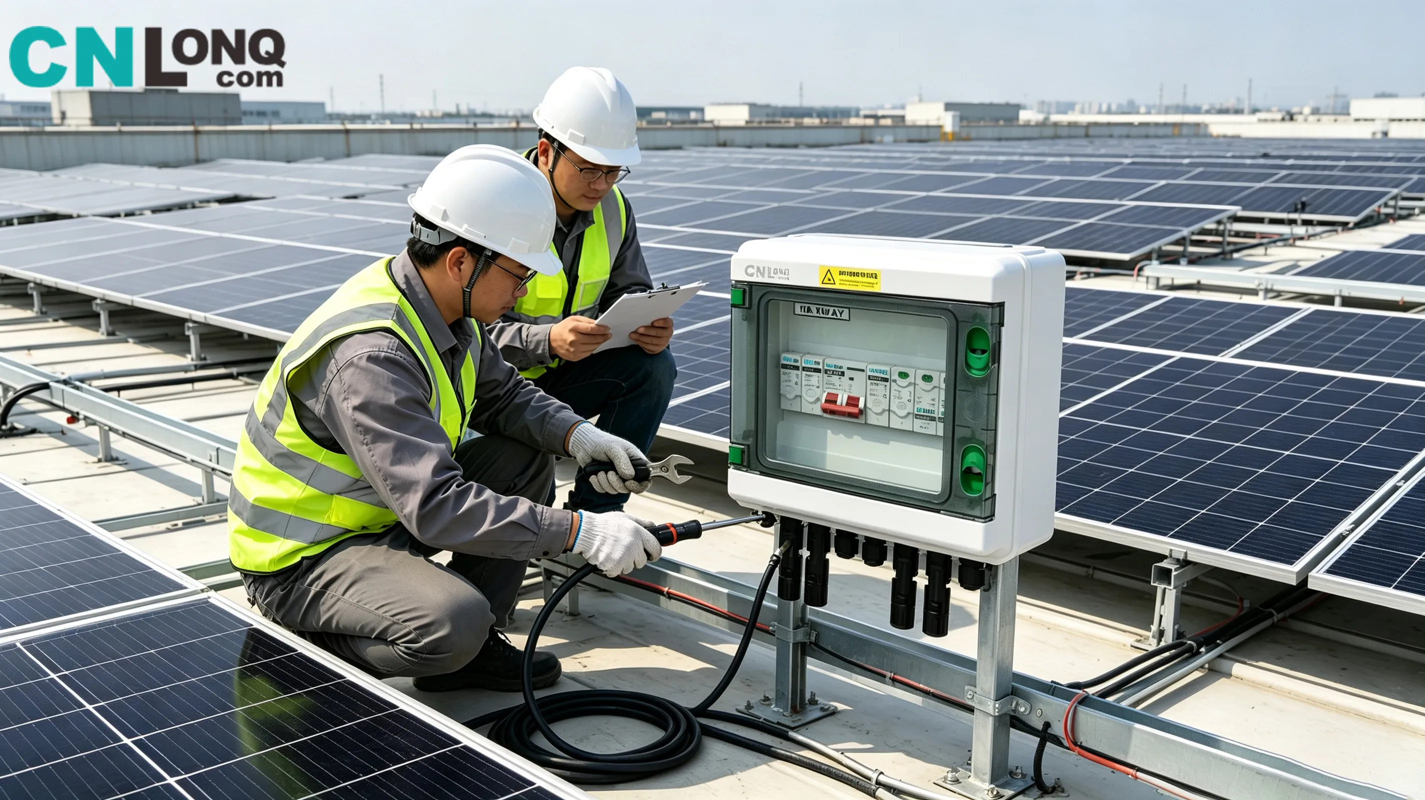
1. Hidden Fire Risks on the PV DC Side
DC electric arcs represent the primary fire hazard for PV DC systems. AC fault arcs extinguish naturally at current zero‑crossing; DC systems lack this zero‑crossing characteristic. Once initiated, DC arcs sustain combustion at temperatures up to several thousand degrees Celsius, rapidly igniting cable insulation, plastic enclosures and surrounding combustible materials. Four major risk sources are outlined below:
Loose connections and connector failure Improperly crimped MC4 connectors, loose or oxidized terminals degrade under thermal expansion and contraction caused by day‑night temperature cycles. Rising contact resistance leads to local overheating and arcing. Loose terminals are particularly common in hot desert environments and rank among the top causes of commercial rooftop PV fires.
Aging and damaged cable insulation Cable abrasion during installation, animal gnawing and long‑term UV exposure crack insulation, triggering short‑circuits and ground faults that produce DC arcs. Latent insulation defects are hardly detectable by visual inspection and are frequently missed during routine site checks.
Fault escalation from hot‑spot effects Shading by dust, vegetation or debris creates module hot‑spots with extreme local temperature rises. Burn‑through of module backsheets causes internal short‑circuits that propagate along DC circuits and result in secondary fire hazards.
Poor‑quality or incorrectly specified DC components DC disconnectors with insufficient arc‑quenching capability, improperly selected SPDs and mismatched fuses may suffer thermal breakdown under over‑voltage or lightning surges. Many sites incorrectly deploy AC‑rated components in DC PV circuits. Unable to interrupt fault currents, these misapplied devices create severe fire risks.
Harsh operating conditions amplify safety risks. Accelerated component ageing and higher DC‑fault probabilities occur in hot desert regions, salt‑spray coastal zones, high‑UV locations and lightning‑prone areas. Since the PV DC side stays live under illumination, fault isolation cannot be achieved by simple power shutdown, adding complexity to emergency response.
2. Multi‑Level Lightning Protection against Surge Over‑Voltages
PV installations operate in open‑air environments. Even without a direct lightning strike, distant lightning induces surge voltages of several thousand volts along long DC cable runs. Such surges can damage module insulation, destroy inverters and DC components and indirectly trigger fires. Reliable PV lightning protection cannot rely solely on AC‑side protective devices. A three‑tier protection system must be implemented: external lightning defence, equipotential earthing and DC‑side surge protection.
Tier 1: External lightning protection and solid earthing Rooftop and ground‑mounted sites shall install lightning conductors and air‑termination systems. All metallic structures including mounting racks, combiner‑box enclosures and equipment housings must be equipotentially earthed. This eliminates potential differences during lightning events and prevents dangerous back‑flashover damage. Earthing installation quality determines overall lightning‑protection performance.
Tier 2: Hierarchical DC‑side SPD protection A common design flaw is installing SPDs only on the inverter AC side while omitting SPDs inside DC combiner boxes. Lightning surges propagating through PV strings can directly destroy inverter DC terminals.
- PV‑specific DC SPDs shall be fitted inside combiner boxes. Type 1 2 combined SPDs are recommended for high‑lightning‑risk utility‑scale plants; Type 2 DC SPDs apply for most residential and commercial rooftop systems.
- AC‑rated SPDs must never be used in PV DC circuits. AC SPDs lack DC‑compliant thermal disconnection mechanisms and pose severe fire risks when failing under DC conditions. This constitutes a critical installation error.
- Adopt cascaded protection: primary protection at combiner boxes plus secondary protection at inverter DC inputs. Minimize SPD wiring lead lengths to limit residual voltage.
Tier 3: Condition monitoring and scheduled replacement Metal‑oxide varistors inside DC SPDs degrade cumulatively after absorbing lightning surges. Many models feature visual failure indicators. Operators shall inspect SPD status regularly and replace units showing fault alarms. Running systems with non‑functional SPDs leaves installations unprotected.
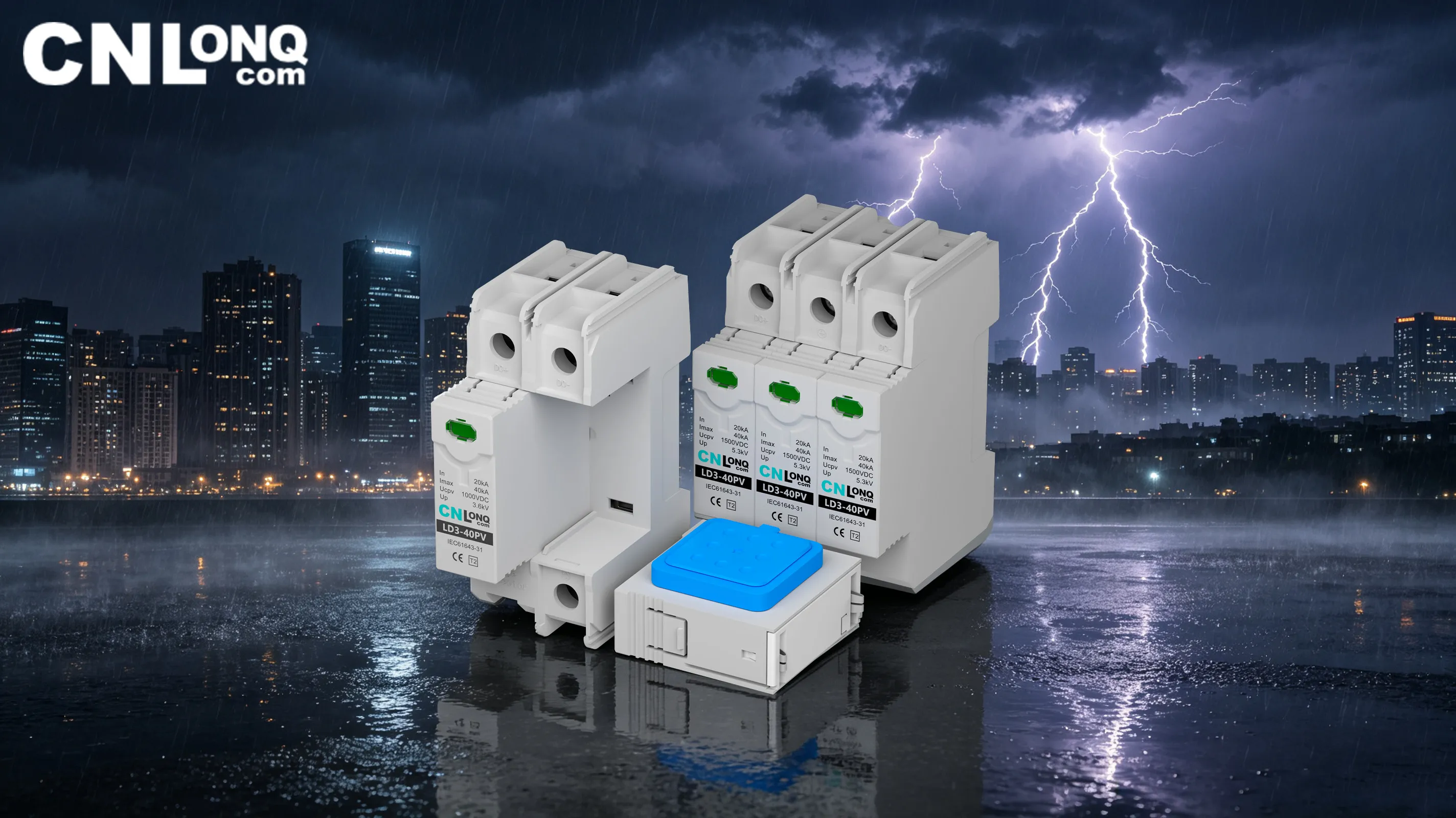
3. Core Selection Principles for PV DC‑Side Components
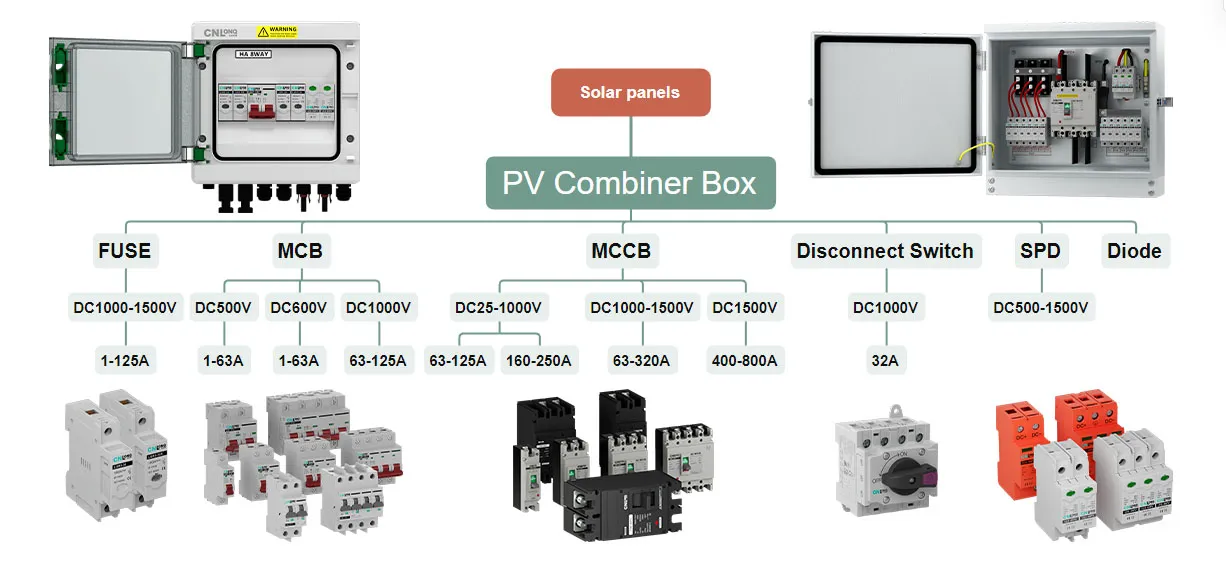
DC disconnectors, DC SPDs, DC fuses and combiner‑box enclosures form four key elements of DC circuits. Procurement decisions should not be price‑driven alone. Rated voltage, arc extinction, flame retardancy, ingress protection and weather resistance must match on‑site operating conditions.
3.1 PV DC Disconnector
DC disconnectors enable safe isolation for maintenance and fault cut‑off. Focus on DC breaking and arc‑quenching performance:
- Rated DC voltage shall be no less than the system maximum voltage. Use 1000 V DC disconnectors for 1000 V systems and 1500 V DC disconnectors for 1500 V systems; derating is prohibited.
- Equipped with dedicated DC arc‑chambers capable of load‑break operation to avoid arcing during switching.
- Enclosure material achieves UL94‑V‑0 flame‑retardant rating to stop fire propagation under high temperatures.
- For outdoor combiner‑box integration, match enclosure IP65 / IP66 ratings for rain, dust and UV resistance.
3.2 PV‑Specific DC Surge Protective Device (SPD)
SPDs are central to lightning mitigation. Four essential parameters must be verified:
- Maximum continuous operating voltage Ucpv: Ucpv ≥ 1.2 × module maximum open‑circuit voltage under low‑temperature conditions. Under‑rated Ucpv causes permanent SPD conduction, thermal runaway and burnout — one of the most frequent selection mistakes. For 1000 V DC systems, Ucpv should reach at least 1100 V.
- Voltage protection level Up: Lower residual voltage delivers better protection; Up must be below the impulse withstand voltage of downstream equipment.
- Integrated thermal disconnector: Triggers safe physical disconnection upon component overheating to prevent fire, paired with visual failure indication.
- Deploy Type 1 2 SPDs for mountainous or utility‑scale sites with frequent lightning; Type 2 SPDs for residential and commercial‑industrial projects. Always select PV‑certified DC SPDs; AC SPD reuse is forbidden.
3.3 DC Fuses
DC fuses provide primary string over‑current protection. Only PV‑certified gPV type DC fuses shall be adopted. Rated current should equal 1.5‑2 times the module operating current. Fuses must rapidly interrupt reverse fault currents to prevent module burnout and DC‑arc hazards.
3.4 Combiner‑box Enclosure and Environmental Adaptation
- Ingress protection rating: minimum IP65 for outdoor deployment; select IP66 for coastal, desert and heavily polluted sites for enhanced water, dust and salt‑mist resistance.
- Material requirements: plastic housings shall use PC ABS composite material with UL94‑V‑0 flame retardancy and UV‑stabilization. Metallic enclosures use cold‑rolled steel or stainless steel with anti‑corrosion coating.
- Optimized internal layout with adequately rated busbars and terminals to avoid excessive internal heat accumulation.
4. Practical Engineering Recommendations to Minimize DC‑Side Hazards
- At the design phase, fully evaluate local lightning risk, temperature profile and system voltage rating. Specify the complete protection package including DC disconnectors, DC SPDs and DC fuses; avoid cost‑driven removal of safety components.
- Source components with complete IEC and UL certifications for PV DC applications. Strictly reject repurposed AC‑spec devices.
- Enforce high‑quality installation practices: standardized connector crimping, secure terminal torquing, mechanical cable protection and minimization of intermediate connections.
- Implement regular O&M workflows: inspect SPD health, terminal temperature and enclosure sealing. Prioritize hazard inspection for ageing legacy PV plants.
Conclusion
While the PV industry pursues higher energy yield and cost reduction, DC‑side safety remains non‑negotiable. Most PV DC‑related fires are preventable. Incidents usually stem from under‑specified components, misapplication of AC‑rated hardware and poor workmanship. By controlling DC‑arc risks, implementing multi‑layer lightning protection and selecting application‑matched certified DC components, plant operators can secure reliable performance across the full 25‑year PV service life and safeguard project returns.
